

 English
 中文简体
中文简体 Español
Introduction to Helical Gear Motor Series for SEW Eurodrive Replacement
When maintaining or upgrading industrial drive systems, selecting an interchangeable gearmotor that matches original mounting dimensions and performance characteristics is critical. The R, F, K, and S series helical gear motors represent four distinct mechanical configurations designed to replace existing units without costly modifications. Understanding their unique torque transmission paths, efficiency profiles, and allowable mounting positions ensures a seamless retrofit for sew eurodrive gear reducer applications.
Each series addresses specific spatial constraints and torque requirements: inline r series helical gear motor for coaxial layouts, parallel shaft f series helical gear motor for high-torque offset drives, right-angle k series helical gear motor for space-limited corners, and s series helical gear motor for extremely high reduction ratios. This guide provides engineering criteria to evaluate these alternatives, backed by comparative data and visual decision tools.
Comparative Specifications and Mounting Dimensions
Interchangeability with existing eurodrive gear reducer footnotes relies on six critical parameters: center distance, shaft diameter, flange pattern, keyway dimensions, input flange, and housing footprint. The table below summarizes typical technical boundaries for each series when used as replacement drives.
| Series | Torque Range (Nm) | Ratio Range (i) | Efficiency (%) | Mounting Options |
|---|---|---|---|---|
| R Series (Inline) | 130 – 18,000 | 1.3 – 289.5 | 94 – 97 | Foot, flange, torque arm |
| F Series (Parallel) | 200 – 25,000 | 4.3 – 245.6 | 94 – 96 | Foot, hollow shaft |
| K Series (Bevel) | 100 – 16,000 | 5.36 – 326.25 | 92 – 95 | Foot, flange, B5/B14 |
| S Series (Worm) | 42 – 4,000 | 6.8 – 15,000 | 70 – 92 | Foot, flange, shaft mount |
For sew eurodrive gear reducer retrofits, the F series often matches parallel shaft installations, while R series is preferred for compact inline replacements. Always verify output shaft orientation and housing free space before final selection.
R series helical gear motor – Compact Inline Solution
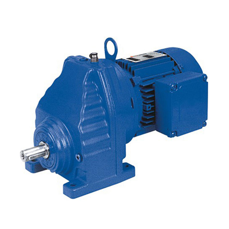
The R series features a coaxial helical gear train, where input and output shafts lie on the same axis. This design minimizes radial loads and provides the highest efficiency among all configurations, typically reaching 97% at nominal load. For gear reducer motor applications requiring direct replacement of inline drives, the R series maintains identical foot dimensions and shaft center heights.
Key Engineering Advantages
- Uninterrupted torque flow with zero offset, reducing bending moments on bearings.
- Available in 12 frame sizes covering power ratings from 0.12 kW to 160 kW.
- Lubrication options: mineral oil (ISO VG 220) or synthetic for extended service intervals.
- Optional backstop for incline conveyors and hoisting duties.
When retrofitting existing machinery, measure the distance from motor mounting face to output shaft shoulder; R series units offer standard C-face adapters that align with IEC and NEMA motors. Typical applications include agitators, screening machines, and metering pumps where coaxial alignment is mandatory.
F series helical gear motor – Parallel Shaft High Torque
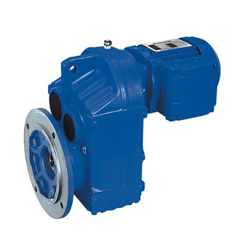
Parallel shaft configurations transfer torque via offset input and output shafts, allowing higher reduction ratios within a single stage compared to inline designs. The parallel shaft helical gear motor excels in heavy-duty conveyors, mixers, and steel mill drives where shock loads are prevalent. Its asymmetric housing distributes thermal load efficiently, enabling continuous operation at ambient temperatures up to 50°C.
Design Characteristics for Retrofit
- Output shaft diameters from 25 mm to 110 mm, matching common industrial standards.
- Double enveloping gear teeth for increased contact ratio (εα > 1.8).
- Integral cooling ribs on housing – surface area enlarged by 22% compared to generic units.
- Available with solid or hollow output shafts (keyed or shrink disc).
For eurodrive gear reducer replacements in apron feeders or bucket elevators, always confirm shaft direction relative to mounting base. The F series allows eight different mounting positions (M1 to M8) without oil leakage when equipped with dual lip seals.
k series helical gear motor – Right Angle Efficiency
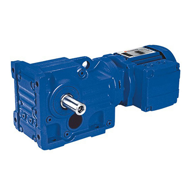
Combining helical input stages with a bevel output stage, the helical-bevel gear motor provides 90-degree torque redirection while maintaining high overall efficiency (up to 95%). This geometry is indispensable when floor space is constrained or where the driven machine requires orthogonal shaft alignment. The K series offers the best compromise between reduction ratio and mechanical efficiency among right-angle drives.
Technical Highlights for Interchangeability
- Bevel gear sets ground according to Klingelnberg standards, ensuring noise levels below 70 dB(A).
- Rigid grey cast iron housing (GGG-40) with integrated torque arm brackets.
- Output torque capacity ranges from 100 Nm to 16,000 Nm across 12 sizes.
- Optional double output shafts for dual-drive applications.
When replacing an existing gear motor reducer with right-angle output, verify the bevel gear hand (spiral direction) to avoid axial thrust reversal. The K series supports both clockwise and counterclockwise output rotation by simply flipping the bevel gear assembly.
S Series Helical-Worm Gear Motor – High Reduction Ratios
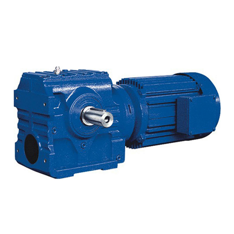
The helical-worm gear motor combines a helical input stage with a worm output stage, achieving reduction ratios up to 15,000:1 in a single compact housing. This design is ideal for intermittent duty applications such as gates, positioning tables, and small hoists. While overall efficiency ranges from 70% to 92%, the self-locking capability (dependent on lead angle) eliminates the need for external brakes in many static load scenarios.
Selection Considerations for Replacement
- Worm gear made of centrifugally cast CuSn12 bronze for high sliding velocity resistance.
- Center distances from 63 mm to 200 mm, directly interchangeable with standard worm units.
- Input speeds up to 3,000 RPM (with synthetic oil for thermal dissipation).
- Thermal power rating typically 30-40% lower than pure helical units – consult duty cycle.
For sew eurodrive gear reducer retrofits in seldom-operated machinery, the S series provides cost-effective high reduction. However, avoid using self-locking worm gears in applications with high vibration or reverse driving (e.g., conveyor backstops). Always specify the oil fill orientation based on mounting position.
Key Selection Criteria for Interchangeable Gearmotors
Choosing between R/F/K/S series involves balancing torque density, spatial constraints, and thermal limits. The following decision matrix compares non-dimensional performance indices for a typical 15 kW, 1460 RPM input motor:
Torque Density (Nm/kg)
R: 4.2 | F: 5.1 | K: 4.6 | S: 2.3
F series offers highest torque per unit mass due to parallel shaft layout.
Axial Length (mm)
R: 285 | F: 415 | K: 320 | S: 380
R series shortest, ideal for space-limited motor compartments.
Typical Service Factor (SF)
All series rated SF=1.25 – 2.0 per AGMA standards. Higher SF for F/K in shock load.
For retrofits, always obtain the original gear reducer motor nameplate data: output torque, speed, and service class. Use the formula: Required output torque (Nm) = (Power (kW) * 9550) / Output RPM. Then select a series where nominal torque exceeds this value by at least 20% for shock safety.
Critical check: Hollow shaft versions of F and K series require precise shrink disc tightening torque – refer to the supplied mounting manual. Improper installation leads to fretting corrosion and shaft damage.
Achieving Seamless Fit: Mounting Dimensions and Adapter Kits
Standardized mounting dimensions for interchangeable gearmotors follow ISO 9409, IEC 60072, and AGMA 9008. The table below lists critical dimensions that must match between the original drive and the replacement R/F/K/S unit:
| Parameter | R Series | F Series | K Series | S Series |
|---|---|---|---|---|
| Foot hole pattern (a x b) | ISO 560 – 800 | ISO 710 – 900 | ISO 560 – 800 | ISO 500 – 710 |
| Output shaft keyway (width x depth) | DIN 6885 (P9) | DIN 6885 (P9) | DIN 6885 (N9) | DIN 6885 (P9) |
| Flange pilot diameter (j6) | 180 – 450 mm | 200 – 550 mm | 180 – 450 mm | 140 – 400 mm |
| Adapter availability for IEC motors | All sizes | All sizes | B5/B14 from size 09 | Limited (size S42+) |
Where original mounting holes deviate by less than 5 mm, use eccentric flanged adapters. For larger discrepancies, consider a torque arm kit (available for all series). Always replace input seals when changing motor adapters to prevent lubricant leakage.
Decision Flowchart for Selecting Replacement Gear Motor
Use this systematic decision tree to narrow down the correct series based on mechanical constraints and performance targets.
Frequently Asked Questions
Q1: Can I directly replace a SEW Eurodrive gear reducer with an R/F/K/S series motor without modifying the base plate?
Yes, all four series are designed to ISO and AGMA standard mounting dimensions. However, always verify foot hole distances and output shaft diameter. The R and F series offer the highest dimensional compatibility with common Eurodrive footprint patterns from sizes 37 to 97. For K and S series, minor adapter plates may be required for older frames.
Q2: Which series provides the highest efficiency for continuous duty applications?
The R series inline helical gear motor achieves the highest efficiency (97%) due to minimal sliding friction and straight gear tooth contact. For right-angle needs, the K series helical-bevel design maintains 95% efficiency, while S series helical-worm should be avoided for continuous high-power operation due to lower thermal limits.
Q3: How do I determine if my application requires a hollow shaft or solid shaft output?
Hollow shafts (available on F and K series) are preferred for direct machine shaft mounting, eliminating coupling alignment. Solid shaft (all series) is standard for foot-mounted or flanged connections. Use hollow shaft when space prevents coupling access or when frequent disassembly is needed.
Q4: What lubrication should I use for a replacement gearmotor operating in cold environments (-20°C)?
Switch to synthetic ISO VG 100 or 150 oil (polyalphaolefin base) to maintain fluidity. For R/F/K series, a fill level reduction of 20% prevents churning losses. Always consult the factory for cold-start viscosity grades. Standard mineral oil is unsuitable below -10°C.
Q5: How do I confirm the correct service factor when replacing an old reducer?
Identify the original duty cycle and load classification (uniform, moderate shock, heavy shock). For uniform loads (conveyors, fans), use SF 1.25; moderate shock (mixers, presses) SF 1.50; heavy shock (crushers, shredders) SF 2.0. Multiply the required output torque by SF and compare to nominal torque tables.
Q6: Can the S series self-locking feature replace a mechanical brake?
Partial self-locking exists for worm ratios above 50:1, but it should not be relied upon for emergency holding or vertical loads due to potential wear. Use a separate brake motor or backstop for hoisting applications. The self-locking efficiency decreases by 30% after 2000 operating hours.


