

 English
 中文简体
中文简体 Español
In the realm of mechanical engineering, the planetary gearbox stands as one of the most efficient and reliable components in power transmission systems. From automotive applications to industrial mach...
See Details
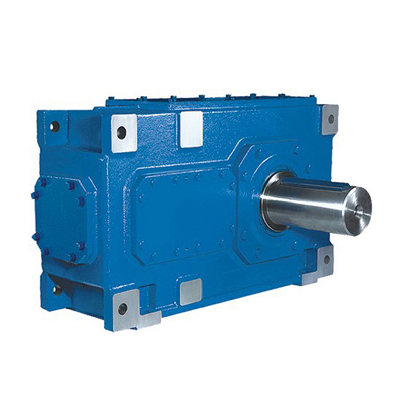
In sectors where mechanical reliability is not optional but foundational, the engineering decisions made around power transmission define operational success or failure. Cement kilns, mining conveyors, steel rolling mills, and marine propulsion systems all share one demand: sustained, high-torque output under continuous load. The H B Series Industrial Gear Units have been engineered specifically to meet that demand, combining helical and bevel gear geometry into a compact, high-efficiency drive package.
This guide examines how these units achieve superior torque density, how engineers should approach selection and installation, and what operational practices extend service life in the most demanding environments.
Torque multiplication is the core function of any industrial gear reducer. When a motor delivers rotational force at high speed and relatively low torque, the reducer transforms that input into the slow, powerful output rotation required by heavy machinery. The ratio between input and output speed determines how much torque is multiplied, minus losses from friction and heat.
The H B Series achieves its performance through a specific geometric combination:
Multi-stage helical bevel configurations can achieve overall ratios from 8:1 to over 400:1 in a single housing, making them the preferred choice for industrial drive solutions where space constraints and torque requirements coexist.
Not all speed reducers gearbox designs are created equal. The H B Series distinguishes itself through a modular architecture that separates input, intermediate, and output stages. This modularity has three practical consequences:
Output ratios are configurable by changing the number of helical stages upstream of the bevel set. Engineers can select 2-stage, 3-stage, or 4-stage arrangements from the same base housing family.
Hollow-shaft, solid-shaft, and shrink-disc variants accommodate direct coupling to driven machinery without intermediate coupling components, reducing alignment error and transmission loss.
Foot-mounted, flange-mounted, and torque-arm configurations let installation engineers adapt the unit to existing plant layouts rather than redesigning support structures.
Correct selection of a reducer gearbox requires more than matching nominal power ratings. Industrial loads impose dynamic conditions that peak well above steady-state values. The H B Series is rated using a service factor methodology that accounts for load classification, daily operating hours, and starting frequency.
| Application Type | Typical Service Factor | Daily Operating Hours | Shock Level |
|---|---|---|---|
| Light conveyors, fans | 1.00 - 1.25 | Up to 10 hrs | Uniform |
| Mixers, bucket elevators | 1.25 - 1.50 | 10 - 16 hrs | Moderate |
| Crushers, ball mills | 1.50 - 2.00 | 16 - 24 hrs | Heavy |
| Mining hoists, rolling mills | 2.00 - 2.50 | Continuous 24 hrs | Very Heavy |
| Excavators, offshore drives | 2.50 and above | Continuous with reversals | Extreme |
When the required output torque is multiplied by the service factor, the result is the design torque the selected unit must comfortably exceed in its rated capacity. Undersizing by even one frame leads to accelerated pitting on tooth flanks and premature bearing failure, typically becoming visible within 3,000 to 5,000 operating hours.
Beyond torque, the output speed of the driven machine constrains ratio selection. Common industrial targets include:
Heat generation is the primary constraint on continuous-duty performance in any gearbox reducer. Every percentage point of efficiency loss translates directly into thermal load that the housing, lubricant, and cooling system must dissipate. The H B Series addresses this through several design disciplines.
Ground helical gears with optimized tooth profiles achieve minimal sliding friction at pitch circle contact.
Mineral or synthetic PAO oils at this grade form adequate elastohydrodynamic films up to 80 degrees C sump temperature.
Cylindrical roller and taper roller bearings selected for the rated load envelope to achieve this design life at full load.
Standard natural convection cooling is adequate for intermittent or lightly loaded continuous duty. For heavy continuous service, the following upgrades are specified:
Field studies across cement and mining installations indicate that maintaining sump oil temperature below 75 degrees C extends seal life by a factor of 2.5 compared with units running at 90 degrees C, with a corresponding reduction in unplanned downtime rates of approximately 40%.
The versatility of the helical bevel industrial gear unit format makes it applicable across a wide range of sectors. Below are the primary industries and their specific demands.
Rotary kilns require extremely slow, highly uniform output rotation to prevent thermal distortion of the kiln shell. The H B Series, when paired with a tangential spring-loaded gear coupling, absorbs the minor rotational irregularities of a long cylindrical shell expanding and contracting over a 24-hour firing cycle. Rated output torques in this sector regularly exceed 500 kNm in large-diameter installations.
Ball mills present a different challenge: high starting torques during media cascade, often reaching 200 to 250% of nominal running torque in the first 15 seconds of each start cycle. The gear unit must accommodate this peak without tooth scoring, which is why hardened and ground tooth flanks are essential, not optional, for this duty.
Underground conveyor drives operate in confined spaces with high humidity and dust contamination. The H B Series IP65 or IP66 sealed housing options prevent ingress while the shaft seals use labyrinth-plus-contact configurations that tolerate shaft deflection from conveyor belt tension variations without air gap formation.
Bucket wheel excavators represent some of the largest torque requirements in any terrestrial machine. Slew drives and crowd drives on such equipment employ multiple synchronized gear units, each carefully load-balanced through electronic torque monitoring to prevent one unit from overloading while adjacent units run light.
Rolling mill main drives demand rapid load changes as bar stock enters and exits the roll gap. The input speed may remain constant while output torque spikes from near-zero to full rated value in under 200 milliseconds. This rate of torque rise places severe demands on gear tooth contact geometry, lubricant film formation, and coupling flexibility. Only gear units designed with adequate safety margins and case-hardened gearing survive repeated thermal and mechanical cycling in these conditions.
Slow-speed mixer and clarifier drives require parallel shaft gearbox or right-angle configurations depending on tank geometry. Continuous 24-hour operation with long mean times between maintenance access means that bearing life, seal durability, and oil change intervals directly impact plant economics. Synthetic lubricant options can extend oil change intervals from 8,000 to 20,000 hours in these moderate-temperature, continuous-duty applications.
No mechanical component consumes more gearbox life prematurely than improper lubrication. The H B Series, like all precision industrial speed reducer designs, depends on maintaining a full elastohydrodynamic (EHD) oil film between gear tooth flanks and rolling element raceways at all operating speeds and temperatures.
| Method | Applicable Output Speed | Advantages | Limitations |
|---|---|---|---|
| Splash (bath) lubrication | Above 80 rpm | No external components, low maintenance | Churning loss at high speeds |
| Pressure circulation with pump | All speeds | Consistent film, filtration, cooling | Pump, filter, and piping required |
| Spray nozzle injection | Below 60 rpm (slow gears) | Direct tooth-face wetting | Requires precise nozzle positioning |
| Grease-packed (sealed bearings) | Auxiliary positions only | Zero leakage risk at seals | Limited re-lubrication access |
Modern industrial practice has moved away from fixed time-based oil changes toward condition-based intervals using oil analysis. Key parameters to monitor include:
The best-specified heavy-duty gear unit will underperform or fail prematurely if installation practices are not followed. The following represent the most impactful installation disciplines for H B Series units in industrial settings.
Shaft misalignment generates radial and axial bearing loads beyond design intent, reducing L10 bearing life dramatically. A misalignment of 0.1 mm at a 200 mm coupling span translates to an angular error of 0.5 milliradians, sufficient to impose measurable additional load on the output bearing set. Laser alignment tools should be used to achieve:
The baseplate supporting the gear unit and motor must be rigid enough to maintain alignment under dynamic load. Recommended practice includes:
Hollow-shaft H B Series units mounted directly on the driven shaft require a torque arm of sufficient stiffness to prevent the housing from rotating under load. The torque arm attachment point must be elastically compliant in the axial direction to accommodate driven shaft thermal expansion without imposing side loads on the gearbox output bearing.
Unplanned stoppages in heavy industry carry costs that dwarf the price of a replacement gear unit. A single unscheduled outage on a cement kiln can exceed 100,000 USD per day in lost production, making predictive maintenance not just technically sensible but economically imperative.
Gear mesh frequency (GMF) monitoring provides the earliest warning of tooth wear or damage. Each gear stage produces a characteristic frequency equal to the number of teeth multiplied by shaft speed. Sidebands around this frequency, when they emerge or grow, indicate:
| Maintenance Action | Interval | Tools Required |
|---|---|---|
| Oil level check | Weekly | Sight glass / dipstick |
| Vibration baseline check | Monthly | Portable vibration analyzer |
| Oil sample for analysis | Every 3 months | Sample port, syringe kit |
| External seal inspection | Every 6 months | Visual, torque wrench |
| Oil change (mineral) | Every 8,000 hrs | Drain, fill fittings |
| Oil change (synthetic) | Every 20,000 hrs | Drain, fill fittings |
| Full internal inspection | Every 50,000 hrs | Disassembly tools, gauges |
Selecting the right industrial gear reducers for a specific application follows a structured engineering process. Each stage filters the available options until a single optimal specification emerges.
Thermal validation in Step 6 is frequently overlooked but critical. Many gear units are mechanically adequate for the torque demand but thermally limited by the ambient environment. A unit rated for 45 kW input at 25 degrees C ambient may derate to 35 kW at 45 degrees C without auxiliary cooling, changing the required frame size entirely.
The H B Series represents one of three primary configuration families available for heavy industrial use. Understanding the comparative strengths and limitations guides appropriate specification for each application.
| Parameter | Helical Bevel (H B) | Parallel Shaft Helical | Worm Gear |
|---|---|---|---|
| Peak Efficiency (per stage) | 97 - 99% | 97 - 99% | 50 - 90% |
| Torque Density | Very High | High | Moderate |
| Output Shaft Angle | 90 degrees (right angle) | Parallel to input | 90 degrees (right angle) |
| Noise Level | Low (helical contact) | Low | Very Low |
| Self-Locking | No | No | Possible (high ratio) |
| Continuous Duty Capacity | Excellent | Excellent | Limited by heat |
| Ratio Range (single unit) | 8:1 to 400:1 | 4:1 to 200:1 | 5:1 to 100:1 |
| Typical Applications | Kilns, mills, conveyors | Conveyors, mixers | Valve actuators, lifts |
For the vast majority of heavy industrial applications demanding continuous operation at high torque in a compact footprint, the helical bevel configuration provides the best combination of efficiency, reliability, and installation flexibility. Worm gearboxes remain relevant where self-locking is required or where very low cost at small power ratings is the primary driver.
The H B Series combines helical gear stages for the primary speed reduction with a bevel gear set at the output, allowing the output shaft to be oriented at 90 degrees to the input. A standard parallel shaft helical gearbox has input and output shafts running parallel or coaxial. The right-angle output of the H B configuration provides significantly greater installation flexibility in equipment where space or drive train geometry requires a change of rotational axis.
Service factor selection depends on three variables: the type of load (uniform, moderate shock, heavy shock), the number of daily operating hours, and the starting frequency. Published service factor tables from gear unit manufacturers or standards bodies such as AGMA and ISO provide reference values. When in doubt, selecting a higher service factor than the minimum required adds cost but substantially extends operational life, particularly in remote or difficult-to-access installation sites.
Yes. Helical bevel gear units are bi-directional by design; the gear geometry does not rely on a specific rotation direction for correct lubrication or load distribution. However, if the application involves frequent or rapid reversals, the service factor should be increased to account for the dynamic tooth loading at reversal, and the coupling and motor must also be rated for reversing duty.
Premature shaft seal failure typically results from one of four causes: excessive oil sump temperature softening the seal lip material, misalignment imposing radial load on the seal, contaminated oil particles abrading the sealing lip, or incorrect installation causing the lip to run eccentrically. Addressing each requires attention to thermal management, precise alignment during installation, clean oil with adequate filtration, and careful seal handling and fitting procedures during maintenance.
Synthetic base oils, particularly polyalphaolefin (PAO) types, offer superior viscosity stability across a wide temperature range, lower pour points for cold-start protection, better oxidation resistance extending oil life, and reduced friction coefficients compared to mineral oils. In continuous-duty industrial applications, these properties translate to lower operating temperatures, longer oil change intervals (up to 20,000 hours versus 8,000 for mineral oil), and measurably improved gear and bearing life due to better film formation at elevated temperatures.
Critical warning signs include: a sustained rise in housing temperature above the normal operating baseline by more than 15 degrees C; new or changing noise patterns particularly grinding, knocking, or high-frequency whining; visible oil leakage from shaft seals or housing joints; unusual vibration levels detected on permanent or portable monitoring equipment; and oil discoloration to black or milky appearance indicating oxidation or water ingress respectively. Any single one of these symptoms warrants investigation before the next scheduled maintenance interval.

In the realm of mechanical engineering, the planetary gearbox stands as one of the most efficient and reliable components in power transmission systems. From automotive applications to industrial mach...
See Details
With the rapid development of industrial technology, mechanical equipment has become increasingly important in all walks of life and has become a key factor in promoting the improvement of productivit...
See Details
In modern industrial transmission systems, efficient, reliable and compact speed reduction devices are one of the core components that ensure the stable operation of mechanical equipment. With its uni...
See Details
In the huge system of modern electrical equipment, single-phase AC motor is an extremely critical basic component, and its presence is everywhere in all areas of life and production. Whether it is hom...
See DetailsRequest for a call today
