

 English
 中文简体
中文简体 Español
In the realm of mechanical engineering, the planetary gearbox stands as one of the most efficient and reliable components in power transmission systems. From automotive applications to industrial mach...
See Details
Industrial powertrain engineering regularly demands redirecting rotary motion through a ninety-degree axis. Deciding between a continuous-rotation speed reducer and a linear-displacement actuator dictates the mechanical efficiency, structural integrity, and positioning precision of the complete machine. Engineers often evaluate two distinct approaches for these torque-transmission profiles: fluid-lubricated gear trains and mechanical power screw systems.
Selecting the optimal configuration requires a comprehensive evaluation of dynamic load profiles, input rotational speeds, operational duty cycles, and output movement characteristics. Misspecifying these parameters can cause premature mechanical wear, thermal runaway, or catastrophic component shear. This analysis explores the technical architecture, performance trade-offs, and selection methodologies for wp worm gear reducer variants, linear positioning jacks, and directional steering gearboxes.
Continuous rotational torque transformation requires fluid-film lubrication and high thermal dissipation, whereas discrete linear positioning relies on axial load support and high mechanical leverage.
The primary differentiation between right angle gearbox configurations centers on the intended output kinematics. Gear reducers are optimized to transform high-speed, low-torque rotary input into low-speed, high-torque rotary output. Conversely, mechanical lifters convert rotary input torque directly into high-force axial linear motion or low-speed, heavy-duty mechanical thrust.
When designing a mechanical lifting system, utilizing standard rotational speed reducers requires complex auxiliary link mechanisms, such as external linkages, heavy-duty crank arms, or rack-and-pinion pairings. This increases system compliance, introduces back-lash accumulation, and expands the mechanical footprint. Conversely, using a specialized linear actuator for continuous high-speed rotary mixing or conveyor propulsion leads to rapid mechanical degradation due to inadequate heat transfer and localized frictional heating along the screw threads.
The configuration of heavy-duty worm-driven reducers centers around a hardened steel worm screw operating perpendicular to a bronze alloy wheel. This sliding contact configuration delivers exceptional torque multiplication and substantial shock dampening in a compact structural frame. These units are configured across three primary macro-topologies based on spatial orientation and staging requirements.
Standard industrial platforms utilize the wpa single-stage worm gearbox as a foundational mechanical driver. The input shaft is positioned beneath the output gear wheel, making it ideal for base-mounted floor installations. The design incorporates integrated cast housing wells that ensure constant immersion of the gear mesh in extreme-pressure lubricants, protecting against high-friction wear. For overhead mountings or ceiling-suspended tracks, the WPS configuration flips the gearing alignment, placing the worm drive shaft above the output wheel shaft to match specific structural frameworks.
Vertical output vectors use the WPO and WPX configurations. These specialized variations orient the low-speed shaft vertically upward or downward, which is ideal for large fluid agitators, clarification tanks, and heavy-duty rotating turntables. This design eliminates the need for auxiliary right-angle redirection modules at the mixing vessel interface.
When operational requirements dictate ultra-low velocity profiles combined with extreme mechanical leverage, single-stage gear sets become impractical due to tooth geometry constraints. Implementing a double-stage worm gearbox addresses this by connecting two distinct reduction stages in a series arrangement. This cascading design multiplies individual reduction ratios, allowing final velocity reductions up to 1:3600.
This dual-stage configuration distributes large mechanical loads across two separate gear housings, protecting the primary input stage from high physical stresses. The primary stage handles high-speed reduction, while the secondary stage manages the high-torque output, protecting the bronze wheel elements from premature structural deformation.
| Gearbox Class | Mechanical Ratio Spectrum | Typical Dynamic Efficiency | Primary Mechanical Stress Profile |
|---|---|---|---|
| WPA Single-Stage | 1:10 to 1:60 | 62 percent to 88 percent | Moderate sliding friction, radial input force |
| WPW Double-Stage | 1:100 to 1:3600 | 25 percent to 55 percent | High thermal accumulation, multi-axis torque loads |
When an application requires precise linear lifting, controlled pushing, or heavy structural tilting rather than continuous rotation, a specialized swl worm gear screw jack is the industry standard. The inner mechanics combine a heavy-duty worm gear set with a precision machined power screw, turning rotary torque into high-capacity axial thrust. This design is highly reliable for large structural lifting projects.
These systems utilize two primary operational designs based on structural integration requirements:
A key safety feature of these actuators is their self-locking worm gearbox profile, which is highly advantageous for vertical positioning systems. High-reduction lead screw ratios generate substantial internal sliding friction. This friction prevents the screw mechanism from back-driving under full load when motor power is cut, protecting personnel and material from sudden drop accidents.
Applications requiring multi-axis synchronization or pure right-angle speed redirection without high reduction ratios benefit from the t series steering spiral bevel gearbox. Unlike sliding-contact worm drives, spiral bevel gear sets rely on rolling-contact mechanics, which significantly increases power transmission efficiency.
Maintains mechanical efficiencies between 94 percent and 98 percent per gear mesh. This minimizes heat generation and makes it ideal for continuous, high-speed automated processes.
Supports versatile shaft layouts, including dual cross-shafts and triple-output branching. This allows a single motor to synchronize multiple mechanical operations simultaneously.
These spiral bevel steering gearbox systems are often combined with linear actuators to construct synchronized mechanical lifting networks. This architecture connects a single prime mover to a central bevel steering gearbox, which splits the mechanical torque across multiple cross-linking shafts to operate several screw jacks simultaneously. This eliminates the risk of uneven lifting speeds that can occur with independent electric motors.
Choosing the correct mechanical drive requires balancing application speed, torque, structural loading style, and operational duty cycles. Selecting the wrong component can lead to rapid thermal failure or structural breakage.
| Mechanical Requirement | WP Gearing Solution | SWL Jack Option | T-Series Spiral Bevel |
|---|---|---|---|
| Primary Motion Profile | Continuous Rotary Output | Discrete Axial Thrust | High-Speed Rotary Redirect |
| Typical Duty Cycle Limits | Continuous (100 percent) | Intermittent (20 percent) | Continuous (100 percent) |
| Mechanical Efficiency | Low to Moderate | Low (Self-Locking) | High (98 percent) |
| Back-Driving Resistance | Partial (High Ratios) | Complete Self-Locking | None (Freely Back-Drives) |
When specifying system components using a worm gear reducer catalogue, engineers must convert all operating parameters into worst-case design demands. This involves applying specific service factors to account for external shock loads, extreme ambient temperatures, and daily operational duration, preventing premature fatigue failure.
Worm-driven systems generate significant internal heat due to the high sliding friction between the steel worm screw and the bronze wheel teeth. This friction converts a portion of the input energy into thermal losses, raising oil temperatures. If unmanaged, this heat breaks down the lubricant film, leading to metal-on-metal contact and rapid tooth wear.
Continuous duty reducers require specialized gear oils fortified with anti-wear and extreme-pressure additives. These lubricants maintain fluid-film strength under high sliding pressures. Cast iron housings are designed with integrated cooling fins to increase surface area and maximize convective heat transfer. For high-power operations, cooling fans can be added to the high-speed input shaft to increase airflow across the housing.
Screw jacks are usually packed with high-viscosity synthetic grease to handle extreme axial loads. Because they operate intermittently, they rely on heat dissipating during non-operational periods rather than continuous fluid circulation.
Standard mechanical designs frequently encounter space limitations, complex mounting constraints, or unique non-standard angles. When standard ninety-degree gearboxes cannot fit within a machine's footprint, a customized angle reducer provides a tailor-made alternative. These custom units modify external mounting flanges, housing dimensions, or internal gear profiles to integrate smoothly into compact or complex machinery layouts.
Modern industrial design relies heavily on modular power transmission. Combining different gearing styles allows engineers to optimize system performance. For instance, pairing a primary bevel reducer with a secondary single-stage worm unit creates an efficient, high-torque right-angle drive. This combination delivers the large gear ratios of worm drives while maintaining higher overall efficiency than dual-stage worm systems, optimizing performance for demanding industrial environments.
Higher reduction ratios require a steeper lead angle on the worm thread. This change in geometry shifts the mesh interaction from rolling contact to sliding contact, increasing friction and converting more mechanical energy into heat.
No. Screw jacks are designed for intermittent duty cycles, typically around 20 percent per hour. Continuous high-speed operation causes rapid thermal expansion along the internal screw threads, which breaks down the grease film and can lock up the mechanism.
External vibration, dynamic shock loads, or using low-viscosity lubricants can overcome the static friction coefficient of a self-locking gear set. In safety-critical applications, a mechanical motor brake should always be used as a secondary safety backup.
T-series gearboxes use spiral bevel gears with rolling contact, achieving efficiencies up to 98 percent. Standard worm gears rely on sliding contact, which typically limits efficiency to between 60 and 85 percent, resulting in higher energy loss.
Dual-stage systems should be specified when an application requires an overall velocity reduction ratio exceeding 1:60. Attempting to achieve such high ratios with a single gear set results in inefficient tooth geometry and low torque capacity.
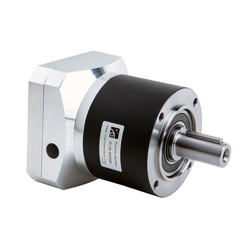
In the realm of mechanical engineering, the planetary gearbox stands as one of the most efficient and reliable components in power transmission systems. From automotive applications to industrial mach...
See Details
With the rapid development of industrial technology, mechanical equipment has become increasingly important in all walks of life and has become a key factor in promoting the improvement of productivit...
See Details
In modern industrial transmission systems, efficient, reliable and compact speed reduction devices are one of the core components that ensure the stable operation of mechanical equipment. With its uni...
See Details
In the huge system of modern electrical equipment, single-phase AC motor is an extremely critical basic component, and its presence is everywhere in all areas of life and production. Whether it is hom...
See DetailsRequest for a call today
