English
 中文简体
中文简体 Español
In the realm of mechanical engineering, the planetary gearbox stands as one of the most efficient and reliable components in power transmission systems. From automotive applications to industrial mach...
See Details
A PL PF Series Precision Planetary Reducer transmits torque through a compact arrangement of concentric gear elements rather than a long chain of parallel shafts. At the center sits the sun gear, which receives input rotation directly from the drive motor. Surrounding it are several planet gears, each meshing simultaneously with the sun gear and an outer ring gear. A carrier structure holds the planet gears in fixed relative position while allowing them to rotate on their own axes as they orbit the sun gear.
This arrangement is what defines an epicyclic planetary gear system. Because load is shared across multiple planet gears rather than carried by a single tooth path, torque distributes evenly around the gear circumference. In practical terms, a three-planet or four-planet gearset can carry proportionally more torque per unit volume than a comparable single mesh gear pair, since each planet gear only bears a fraction of the total transmitted load.
Three structural elements decide how a given planetary gear set performs in service:
A conventional parallel shaft gearbox transmits torque along a straight line of meshing gear pairs, with each stage stacked in sequence. An epicyclic gearbox instead nests each stage inside the same housing diameter, so torque capacity scales with the number of load-sharing planet gears rather than with additional housing length. For applications where mounting space is limited, this difference becomes the deciding factor in gearbox selection.
| Characteristic | Planetary Gearbox | Parallel Shaft Gearbox |
|---|---|---|
| Torque per housing volume | High, load shared across planets | Moderate, single mesh per stage |
| Input/output shaft alignment | Coaxial | Offset between stages |
| Radial bearing load on output | Balanced, low net radial force | Higher, single-side tooth load |
| Typical backlash range | Low to ultra-low with precision grinding | Moderate, depends on shaft count |
The coaxial arrangement of a planetary transmission gear also simplifies mechanical integration. Because the output shaft sits on the same centerline as the input shaft, a planetary gearbox can be mounted directly behind a servo motor without an offset bracket, which reduces both footprint and the number of alignment adjustments needed during installation.
The gear reduction ratio of a planetary gearset depends on the relative tooth counts of the sun gear and ring gear, along with which element is held stationary. In a common configuration where the ring gear is fixed to the housing, the sun gear drives the planet gears, and the carrier delivers output rotation, a single stage typically produces a reduction somewhere in the range of three to ten to one, depending on tooth count proportions.
When an application calls for a larger reduction than a single stage can practically deliver without oversized gear teeth, designers stack a second stage behind the first. Each additional stage multiplies the ratio of the previous stage, so two moderate single-stage ratios combine into a much larger overall reduction while keeping individual gear teeth within a manufacturable size range.
A two-stage epicyclic gearbox distributes the total reduction across two smaller ratio jumps, which generally produces smoother torque transfer and lower audible noise than attempting the same overall ratio in a single stage with very small sun gear teeth.
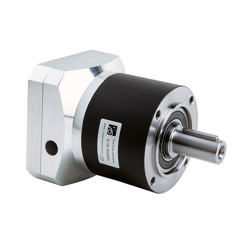
Servo motor matching is not simply a matter of connecting any planetary gearbox to any motor shaft. The gearbox must accommodate the motor's rated speed, its inertia characteristics, and the mounting flange pattern, while also delivering the torque multiplication the application needs at the output.
Three factors most commonly determine whether a planetary gearset is a good match for a given servo motor:
| Factor | Why It Matters |
|---|---|
| Rated input speed | Exceeding the gearbox input speed rating accelerates bearing and gear tooth wear |
| Reflected inertia ratio | A mismatch between motor inertia and reflected load inertia can cause servo loop instability |
| Flange and shaft coupling | Determines whether direct mounting is possible or an adapter is required |
For precision motion control tasks such as pick-and-place positioning or coordinated multi-axis motion, keeping the reflected inertia ratio within a range the servo drive can tune effectively is often more important than maximizing the reduction ratio itself. Oversizing the reduction ratio beyond what the application needs can slow dynamic response even though it increases available torque.
Backlash is the small amount of rotational play between meshing gear teeth, measured in arc-minutes at the output shaft. In applications like indexing tables, robotic joints, or optical positioning stages, even a few arc-minutes of backlash can translate into measurable positioning error at the end effector.
Reducing backlash generally requires tighter manufacturing tolerances on tooth profile and pitch, along with more precise control of axial and radial clearances between the sun gear, planet gears, and ring gear. This added precision typically increases both manufacturing cost and lead time, so specifying a backlash grade beyond what the application actually requires adds expense without a corresponding functional benefit.
Because a coaxial gearbox keeps input and output shafts on a single centerline, mounting a planetary reducer behind a servo motor usually requires only a flange adapter and a shaft coupling, rather than a separate mounting bracket to correct for offset shafts. This simplifies both initial installation and future motor replacement, since the gearbox position relative to the driven equipment does not change.
Space savings become most apparent in multi-axis equipment, where several drive units must fit within a shared enclosure. A coaxial arrangement lets the gearbox occupy roughly the same footprint as the motor itself, rather than extending the assembly sideways.
| Design Aspect | Single-Stage | Multi-Stage |
|---|---|---|
| Typical reduction ratio range | 3:1 to 10:1 | 10:1 to 100:1 or higher |
| Overall length | Shorter | Longer per added stage |
| Efficiency | Higher, fewer meshing losses | Slightly lower per additional stage |
| Best suited for | Moderate reduction, compact footprint | High reduction, high torque multiplication |
Efficiency loss across additional stages is generally small per stage but becomes relevant in continuous duty applications where cumulative heat generation affects lubricant life. When a required reduction ratio can be achieved with either one heavily reduced stage or two moderately reduced stages, the two-stage option is often preferable for smoother torque delivery, even though it adds axial length.
A well-matched planetary transmission gear can run for many years with minimal intervention, provided lubrication and load conditions stay within rated limits. Routine attention to a small set of factors accounts for most of the difference between long service life and premature failure.
Maximum torque is set by the load-carrying capacity of the planet gear teeth, the carrier bearing rating, and the output shaft diameter. Increasing the number of planet gears in mesh raises torque capacity without enlarging the housing.
Gear reduction ratio describes the change in rotational speed between input and output. Torque multiplication is closely related but also depends on mechanical efficiency, since some torque is lost to friction within the gear mesh.
Lower backlash reduces one source of positioning error, but overall accuracy also depends on servo drive tuning, encoder resolution, and mechanical stiffness of the coupling and driven structure.
Within a compatible flange and shaft range, yes, but the reflected inertia ratio and rated input speed should be rechecked whenever the motor size changes to confirm the pairing still suits the application.
Splitting a large reduction across two stages keeps individual gear tooth sizes within a practical manufacturing range and generally produces smoother, quieter operation than a single stage with extreme tooth count ratios.
In the realm of mechanical engineering, the planetary gearbox stands as one of the most efficient and reliable components in power transmission systems. From automotive applications to industrial mach...
See Details
With the rapid development of industrial technology, mechanical equipment has become increasingly important in all walks of life and has become a key factor in promoting the improvement of productivit...
See Details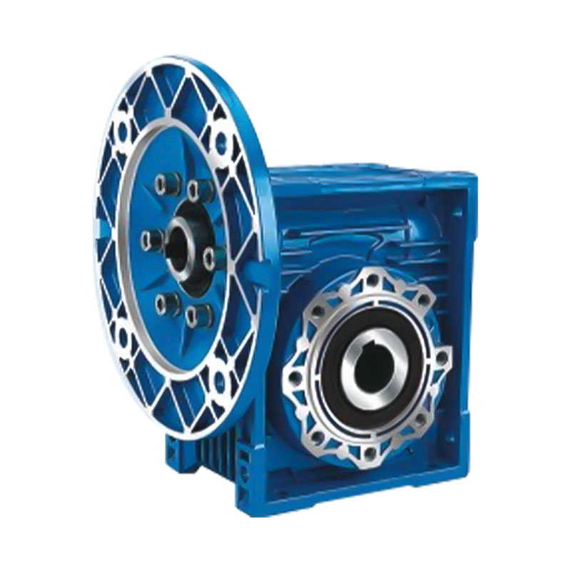
In modern industrial transmission systems, efficient, reliable and compact speed reduction devices are one of the core components that ensure the stable operation of mechanical equipment. With its uni...
See Details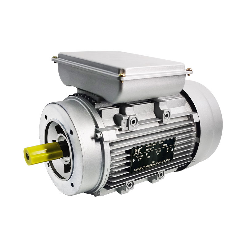
In the huge system of modern electrical equipment, single-phase AC motor is an extremely critical basic component, and its presence is everywhere in all areas of life and production. Whether it is hom...
See DetailsRequest for a call today