English
 中文简体
中文简体 Español
In the realm of mechanical engineering, the planetary gearbox stands as one of the most efficient and reliable components in power transmission systems. From automotive applications to industrial mach...
See Details
A worm gear reducer converts rotational motion between two shafts positioned at a right angle, using a threaded worm shaft that meshes with a toothed worm wheel gear. Unlike parallel-shaft gear sets, the WP worm gear reducer family relies on sliding contact between the worm and worm wheel rather than rolling contact, which is the root cause of both its strengths and its efficiency limitations.
This sliding action gives worm drives two practical advantages that helical or bevel systems cannot match as easily: compact right-angle transmission and a natural self-locking effect at steep lead angles, which prevents back-driving when the input stops. That self-locking trait makes worm and wheel gear sets a common choice for lifting equipment, conveyor inclines, and holding applications where unintended reverse rotation is a safety concern.
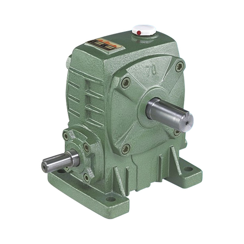
A single-stage worm and worm wheel gear assembly showing the right-angle shaft arrangement
The trade-off is friction. Because the worm gears slide against each other rather than roll, a meaningful portion of input energy is lost as heat at the tooth interface. Understanding where that loss comes from is the first step toward selecting a reducer that meets both torque and thermal requirements.
Efficiency in a worm drive is not a fixed number. It shifts with lead angle, reduction ratio, surface finish, lubricant viscosity, and load level. Two reducers with identical housings can perform very differently once ratio and lubrication are factored in.
| Reduction Ratio Range | Typical Efficiency | Common Use Case |
|---|---|---|
| 5:1 to 10:1 | 75 percent to 85 percent | General conveying, moderate speed reduction |
| 15:1 to 30:1 | 60 percent to 75 percent | Mixing, packaging line drives |
| 40:1 to 60:1 | 45 percent to 60 percent | Slow-speed positioning, holding loads |
| Above 60:1 | Below 45 percent | High-ratio single stage, or better served by double stage |
These ranges are general guidance rather than guarantees, since actual figures depend on manufacturing tolerances, lubricant grade, and duty cycle. What matters for selection is the trend: as ratio climbs, efficiency drops, and at some point a double-stage design becomes more practical than pushing a single stage to an extreme ratio.
Choosing between a single reduction and a stacked double reduction is one of the most consequential decisions in worm drive selection, because it affects footprint, efficiency, and achievable ratio range at the same time.
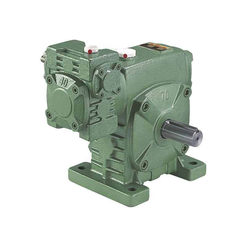
A double-stage worm gearbox pairing two reduction sets in sequence
The WPA Single-Stage Worm Gearbox uses one worm and wheel set to achieve the full ratio in a single mesh. It is the more efficient option whenever the required ratio falls within a moderate range, since power passes through only one sliding contact point.
A Double-Stage Worm Gearbox connects two single-stage units so the output of the first becomes the input of the second, multiplying the two individual ratios together. This allows extremely high overall ratios in one compact housing but compounds frictional losses, since the input energy now passes through two sliding meshes instead of one.
| Characteristic | Single-Stage | Double-Stage |
|---|---|---|
| Typical ratio range | Up to roughly 60:1 | Roughly 60:1 up to several thousand to one |
| Relative efficiency | Higher, single mesh loss only | Lower, losses compound across two meshes |
| Housing footprint | Smaller, single mesh chamber | Larger, two chambers in sequence |
| Best fit | General speed reduction, moderate torque multiplication | Very slow output speed, high torque multiplication, tight ratio precision |
A practical rule of thumb: if the target ratio can be reached with a single stage without pushing lead angle to an inefficient extreme, the single-stage unit is almost always the better choice on energy and heat grounds. Double-stage designs earn their place specifically when the application genuinely needs an output speed or holding torque that a single mesh cannot deliver economically.
Every worm drive trades speed for torque. As the worm turns, each full rotation advances the worm wheel gear by only a small number of teeth, so the output shaft turns slower than the input while available torque rises in roughly the same proportion, minus mechanical losses.
In practical terms, a higher numerical ratio means a bigger gap between input and output speed, and a larger available torque multiplier at the output shaft, provided the gearbox is sized correctly for the load. Selecting ratio is therefore not just about hitting a target output speed; it also means confirming the reducer's torque rating comfortably covers the driven load, including any startup or shock loading the application experiences.
Because worm and wheel gear teeth slide rather than roll against each other, lubricant film integrity has an outsized effect on both efficiency and wear rate compared with other gear types. A thin or degraded film increases metal-to-metal contact, raising both friction losses and the risk of pitting on the wheel teeth.
| Operating Condition | Recommended Oil Check | Recommended Oil Change |
|---|---|---|
| Light duty, ambient temperature | Every 3 months | Every 12 months |
| Continuous duty, moderate load | Every month | Every 6 months |
| Heavy duty, high ambient heat | Every 2 weeks | Every 3 to 4 months |
Beyond scheduled changes, watching for discoloration, a burnt smell, or metallic particles in the oil gives early warning of tooth wear before it becomes a functional failure. Combined with periodic backlash checks, this kind of routine inspection extends service intervals and reduces the chance of unplanned downtime.
Selecting the right reducer is a sequence of narrowing decisions rather than a single calculation. The diagram below outlines the general path from application requirements to a final unit choice.
Once ratio and stage type are settled, remaining decisions center on mounting configuration, shaft orientation, and duty cycle. A gearbox that is thermally rated for intermittent duty will run hotter than expected if placed into continuous operation, so matching the duty rating to actual run time is as important as matching torque and ratio.
Worm drives are not always the right answer. Helical gear reducers use rolling contact between teeth, which generally delivers higher efficiency, but they do not offer the same compact right-angle layout or inherent self-locking behavior.
| Factor | Worm Drive | Helical Drive |
|---|---|---|
| Typical efficiency | 45 percent to 85 percent depending on ratio | 95 percent to 98 percent per stage |
| Shaft arrangement | Right angle, compact | Parallel or in-line, often longer |
| Self-locking capability | Yes, at steep lead angles | No, requires a separate brake if holding is needed |
| Noise level | Generally quieter due to sliding contact | Can be louder at high speed without extra damping |
| High ratio in one stage | Achievable, though efficiency drops | Usually needs multiple stages for very high ratios |
In practice, the decision often comes down to layout constraints and whether self-locking is a functional requirement. When space is tight, the drive must sit at a right angle, or a load must hold position without power, a worm and worm wheel gear set is frequently the more practical choice even with its efficiency trade-off.
The worm and worm wheel gear mesh relies on sliding contact rather than rolling contact, which generates more friction and heat, particularly at shallow lead angles and high reduction ratios.
In most cases yes, because power passes through two sliding meshes instead of one. Double-stage units are chosen when the required ratio or torque cannot be reached practically with a single stage, not because they are more efficient.
Frequency depends on duty cycle and ambient heat, but a general guide is monthly checks for continuous-duty operation and quarterly checks for light-duty applications, with changes on a longer schedule as outlined in the maintenance table above.
Many worm drives with steep enough lead angles are self-locking, meaning the output cannot back-drive the input. This depends on lead angle and lubrication condition, so it should be confirmed for the specific unit rather than assumed universally.
Rising operating temperature, unusual noise, visible backlash increase, or discolored and metallic-particle-laden oil are the most common early indicators of wear that warrant inspection.
Helical reducers are generally preferable when efficiency is the priority, when self-locking is not required, and when the shaft layout does not need a right-angle configuration.
In the realm of mechanical engineering, the planetary gearbox stands as one of the most efficient and reliable components in power transmission systems. From automotive applications to industrial mach...
See Details
With the rapid development of industrial technology, mechanical equipment has become increasingly important in all walks of life and has become a key factor in promoting the improvement of productivit...
See Details
In modern industrial transmission systems, efficient, reliable and compact speed reduction devices are one of the core components that ensure the stable operation of mechanical equipment. With its uni...
See Details
In the huge system of modern electrical equipment, single-phase AC motor is an extremely critical basic component, and its presence is everywhere in all areas of life and production. Whether it is hom...
See DetailsRequest for a call today