English
 中文简体
中文简体 Español
In the realm of mechanical engineering, the planetary gearbox stands as one of the most efficient and reliable components in power transmission systems. From automotive applications to industrial mach...
See Details
Selecting a high-efficiency motor is only half of the engineering problem in an industrial drive system. The other half is the mechanical transmission that carries torque from the motor shaft to the driven load. When a premium-efficiency motor is bolted to a poorly matched gearbox, much of the energy gained at the motor terminals is lost again in gear meshing, bearing friction, and misalignment. Field measurements on conveyor and mixing applications commonly show that a properly matched motor and reducer pairing can recover 6 to 10 percent more usable output torque compared to a mismatched combination running the same duty cycle.
This is why powertrain planning should treat the motor and the reducer as a single functional unit rather than two separate purchases. The housing material, winding class, gear ratio, and lubrication method all interact to determine the real-world energy bill of a machine over its service life, not just the nameplate rating of the motor alone.
Key point: Efficiency losses in a drivetrain accumulate at every mechanical interface. Matching motor output characteristics to reducer input requirements reduces cumulative losses across the full transmission path.
The ye3 series three-phase aluminum alloy housing asynchronous motor is built around three design priorities that directly affect how much of the input electrical energy reaches the output shaft as usable mechanical work.
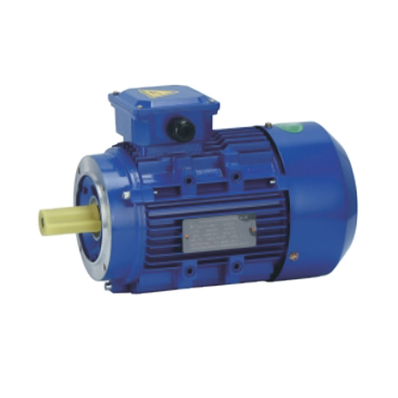
Aluminum housings also bring a secondary but often overlooked benefit: faster thermal response. Because aluminum conducts heat more readily than cast iron, the motor surface reaches thermal equilibrium sooner, which allows more accurate temperature-based condition monitoring and reduces the risk of localized hot spots inside the winding cavity.
| Design Element | Typical Benefit |
|---|---|
| IE3 winding class | Reduced electrical losses at partial and rated load |
| Aluminum alloy frame | Faster heat dissipation, lower installed weight |
| Optimized rotor design | Improved slip control and speed consistency |
| Sealed bearing arrangement | Reduced maintenance frequency in dusty environments |
A parallel shaft gear reducer transmits torque through helical gear stages arranged so the input and output shafts remain parallel to one another. This layout is widely used because it offers a favorable balance between transmission efficiency, compact footprint, and load capacity compared to right-angle or worm gear alternatives.
Three sources of mechanical loss determine how much of the motor output actually reaches the load through a reducer:
Well-designed parallel shaft units typically achieve stage efficiencies in the range of 96 to 98 percent per gear stage under normal load, meaning a two-stage reducer can still deliver overall mechanical efficiency above 92 percent when gear quality, alignment, and lubrication are properly controlled. This makes the parallel shaft configuration a practical choice for applications where minimizing cumulative drivetrain loss matters as much as torque multiplication.
Reducer selection should start with the driven load characteristics, not the catalog page. Shock load frequency, duty cycle, ambient temperature, and required output torque all shape which reducer geometry is appropriate. The comparison below summarizes common characteristics of reducer types encountered in general industrial service.
| Reducer Type | Typical Efficiency Range | Footprint | Best Suited For |
|---|---|---|---|
| Parallel shaft helical | 92 to 97 percent | Compact, low profile | Conveyors, mixers, general material handling |
| Helical-bevel | 90 to 96 percent | Right-angle, moderate | Applications requiring 90 degree shaft output |
| Worm gear | 50 to 90 percent | Very compact | High ratio, low duty cycle applications |
| Planetary | 94 to 98 percent | Very compact, coaxial | High torque density, precision positioning |
For continuous duty applications where energy cost accumulates over long operating hours, parallel shaft and planetary designs generally offer the strongest efficiency retention. Worm gear units remain useful where space is extremely limited and duty cycles are intermittent, since their lower efficiency has less cumulative cost when run intermittently rather than around the clock.
An compact speed reducer paired directly with a three-phase motor through a rigid or flexible coupling forms what is commonly referred to as an integrated motor reducer drive. This arrangement reduces the number of separate mounting points, shortens the mechanical transmission path, and simplifies shaft alignment compared to belt or chain-coupled arrangements.
Mounting orientation also affects long-term reliability. Foot-mounted assemblies are common where floor space allows, flange-mounted units suit machines with limited footprint, and shaft-mounted arrangements eliminate the coupling entirely by seating the reducer output directly on the driven shaft. Each configuration changes how radial and axial loads are carried by the reducer bearings, which should be factored into the load rating check during selection.
The efficiency benefit of a well-matched motor and reducer pairing scales with operating hours. Applications that run near continuous duty see the largest cumulative energy savings, while intermittent applications benefit more from reduced maintenance frequency and longer bearing life.
| Application | Typical Duty Cycle | Primary Benefit of Matched Pairing |
|---|---|---|
| Belt conveyors | Continuous, multi-shift | Lower cumulative energy cost over long run hours |
| Industrial mixers | Continuous with variable load | Stable output speed under load fluctuation |
| Packaging lines | Intermittent, cyclic | Reduced wear from frequent start-stop cycles |
| Material handling hoists | Intermittent, load-variable | Consistent torque delivery at partial load |
In continuous duty conveyor applications specifically, small efficiency gains compound significantly. A drive operating 20 hours per day for a full year accumulates roughly 7,300 operating hours, so even a few percentage points of efficiency improvement at the motor-reducer interface translate into a meaningful reduction in electricity consumption over that period.
Efficiency gains from a well-matched motor and reducer pairing only hold up over time if the assembly is maintained correctly. The following practices help preserve both efficiency and service life.
Practical note: Vibration and temperature trends over time are usually more informative than single point-in-time readings when assessing drivetrain condition.
An electric motor reducer is a gearbox specifically paired and often flange-mounted to a motor as a single assembly, while a standalone gearbox is selected and coupled separately, which allows more flexibility in motor choice but requires additional alignment work during installation.
Aluminum conducts heat more efficiently than cast iron, so the motor surface sheds heat faster, which helps keep internal winding temperature within design limits during sustained operation in warmer ambient conditions.
IE3 is an efficiency classification that defines a minimum efficiency level a motor must meet at rated load, based on standardized testing. Motors in this class generally have lower internal electrical and mechanical losses than lower efficiency classes of the same power rating.
Sizing starts with the required output torque and speed, then applies a service factor based on load shock, duty cycle, and starts per hour, followed by checking that the selected reducer's rated output torque and thermal capacity exceed the calculated requirement with adequate margin.
Change intervals depend on operating temperature, duty cycle, and lubricant type, but as a general practice, oil condition should be checked at regular scheduled intervals and changed sooner if operating temperature or load conditions exceed normal design assumptions.
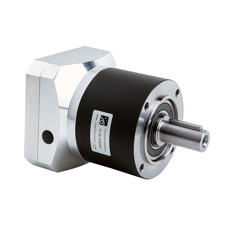
In the realm of mechanical engineering, the planetary gearbox stands as one of the most efficient and reliable components in power transmission systems. From automotive applications to industrial mach...
See Details
With the rapid development of industrial technology, mechanical equipment has become increasingly important in all walks of life and has become a key factor in promoting the improvement of productivit...
See Details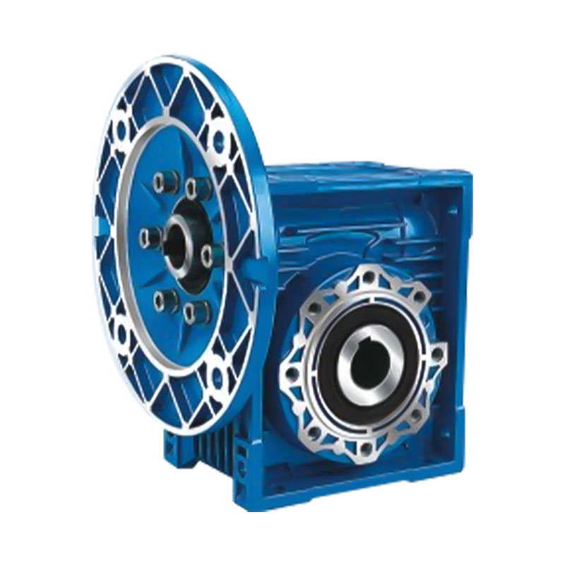
In modern industrial transmission systems, efficient, reliable and compact speed reduction devices are one of the core components that ensure the stable operation of mechanical equipment. With its uni...
See Details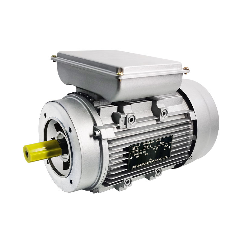
In the huge system of modern electrical equipment, single-phase AC motor is an extremely critical basic component, and its presence is everywhere in all areas of life and production. Whether it is hom...
See DetailsRequest for a call today