English
 中文简体
中文简体 Español
In the realm of mechanical engineering, the planetary gearbox stands as one of the most efficient and reliable components in power transmission systems. From automotive applications to industrial mach...
See Details
A bevel gear is a toothed component cut on a conical surface, designed to transmit rotary motion and torque between two shafts whose axes intersect, most commonly at a ninety degree angle. Unlike parallel-shaft gear sets, bevel gears redirect the direction of power flow while maintaining a fixed speed ratio, which makes them indispensable wherever a compact right-angle drive is required inside a machine frame that cannot accommodate a straight shaft run.
Within this broad category, engineers typically select from three tooth geometries depending on load, noise tolerance, and shaft offset requirements. A straight bevel gear has teeth cut along a line that converges at the cone apex, offering simple manufacturing but generating more impact noise under load. A spiral bevel gear curves the tooth line across the face width, so multiple teeth remain in contact at any instant. This gradual engagement spreads the load across a larger contact area, reduces vibration, and allows the gearbox to carry substantially higher torque at a given size compared with a straight-tooth design.
A miter gear is a special case of the bevel gear family where both mating gears share an identical tooth count, producing a one-to-one speed ratio while still changing the direction of rotation by ninety degrees. Miter gears are commonly specified in instrumentation drives, valve actuators, and other applications where directional change matters more than speed reduction.
A hypoid gear differs from a true bevel gear in that the pinion and gear axes do not intersect; instead, the pinion axis is offset below or above the gear axis. This offset allows a larger, stiffer pinion shaft and a smoother, quieter mesh, which is why hypoid gears are frequently chosen in heavy vehicle drive axles and high-torque industrial reducers where shaft offset simplifies housing layout and bearing support.
Choosing among these geometries is rarely arbitrary. Load magnitude, duty cycle, permissible noise level, lubrication regime, and available envelope space all influence the decision, and a mismatched selection tends to surface later as premature pitting, scoring, or bearing failure rather than an immediate breakdown.
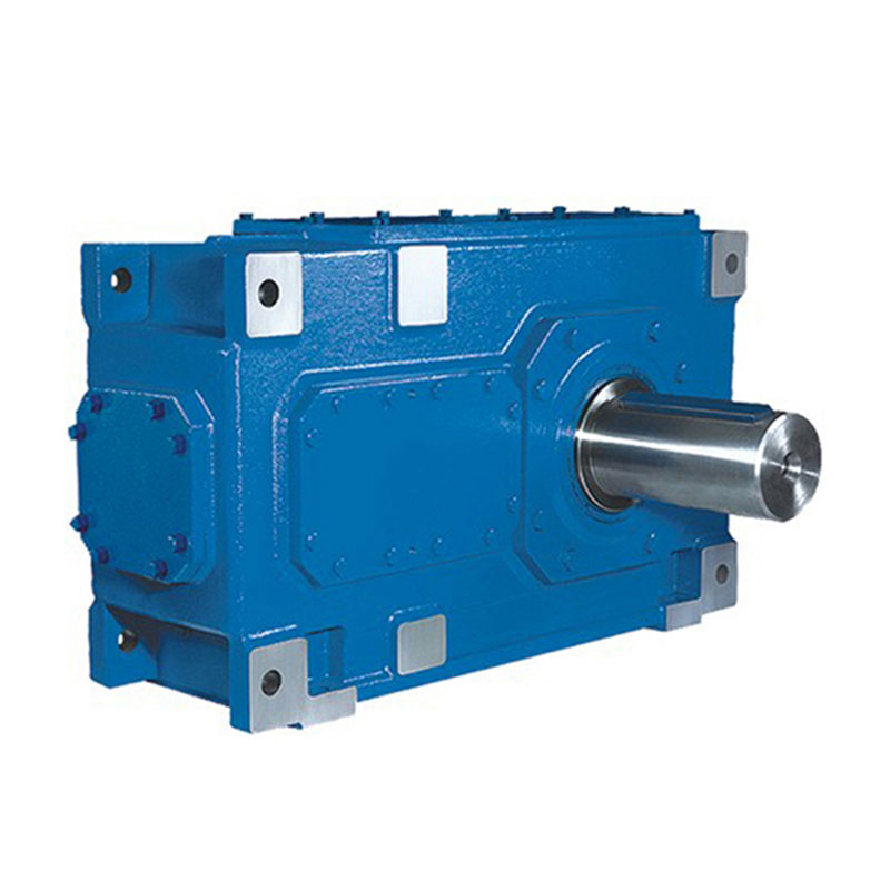
Right-angle industrial reducers built around spiral bevel gear sets are engineered to absorb radial, axial, and overhung loads simultaneously, which is a demanding combination compared with in-line helical or cylindrical gear stages. The h b series industrial gear units illustrate this principle well: a compact cast housing carries the input and output shafts on opposing faces, with tapered roller bearings positioned to resist the combined thrust generated when spiral bevel teeth mesh under load.
Heavy-duty torque transmission through a right-angle stage places three specific demands on the housing and bearing arrangement:
In practical terms, industrial power transmission systems built on this architecture are found in mixers, conveyor drives, agitators, and rotary equipment where a compact footprint and a direction change are both required. The gear ratio range achievable in a single bevel stage is typically modest compared with worm or planetary reducers, so many industrial gear units combine a bevel stage with a helical or planetary reduction stage to reach the final output speed while keeping the right-angle bevel section focused on direction change and primary torque capacity.
Selecting a unit rated well above the nominal running torque, rather than at the calculated minimum, remains one of the most cost-effective ways to extend service intervals, since bevel gear wear accelerates non-linearly once contact stress exceeds the design envelope for the tooth surface finish and lubricant film thickness in use.
Mounting orientation is another practical detail that affects how a right-angle unit performs in service. A foot-mounted housing bolted to a fixed frame behaves differently under thermal expansion than a flange-mounted unit bolted directly to a driven machine, because the flange arrangement ties the gearbox output more rigidly to the load shaft and reduces the tolerance for any residual misalignment. Specifiers who overlook this distinction sometimes find that a unit performing well in one orientation develops uneven bearing wear once it is installed in a different mounting configuration on a similar machine.
Once the basic tooth geometry has been selected, the next practical decision is matching the gear ratio and mounting configuration to the actual duty cycle of the machine rather than to a generic catalog rating. Two machines with identical horsepower requirements can call for very different gearbox specifications once starting torque, shock loading, and ambient conditions are taken into account.
Several factors typically drive this second round of selection:
A gear ratio chosen purely to hit a target output speed, without reference to these secondary factors, often turns out to be technically correct on paper while still under-performing in the field over the first year of continuous operation. Reviewing the full duty cycle profile before finalizing a ratio selection remains one of the more reliable ways to avoid a costly early replacement and unplanned production downtime.
Selecting between these three configurations is easier when the trade-offs are placed side by side. The table below summarizes the practical differences that typically guide a specification decision.
| Attribute | Straight Bevel | Spiral Bevel | Hypoid |
|---|---|---|---|
| Tooth contact | Single tooth, abrupt engagement | Gradual, overlapping engagement | Sliding, overlapping engagement |
| Noise level | Higher | Lower | Lowest |
| Torque capacity per size | Moderate | High | Highest |
| Shaft arrangement | Intersecting axes | Intersecting axes | Offset axes |
| Relative manufacturing cost | Lower | Moderate | Higher |
| Typical duty | Light to moderate, intermittent | Continuous, heavy-duty | Continuous, very heavy-duty |
A straight bevel gear remains a reasonable choice for slow-speed, light-duty, or intermittent applications where cost sensitivity outweighs noise or torque density concerns, such as simple hand-operated valve linkages. Once continuous operation, higher speed, or heavier torque enters the picture, a spiral bevel gear generally becomes the more economical long-term choice because its smoother engagement reduces both noise complaints and the frequency of bearing replacement. Hypoid arrangements are reserved for the most demanding duty cycles, where the offset pinion geometry allows a larger, stiffer shaft to be packaged into a housing that would otherwise be too small to support the load.
A well-engineered gear housing does far more than enclose the gear set; it is the structural element that keeps the pinion and gear in the correct relative position under every load condition the machine will encounter. Three design factors deserve particular attention.
Ribbing patterns cast into the housing walls near the bearing bores resist deflection under peak torque spikes. Insufficient rigidity allows the housing to flex, which shifts the contact pattern toward one edge of the tooth face and concentrates stress on a narrow band rather than the full designed contact area.
Tapered roller bearings supporting bevel pinions typically require a specific preload, adjusted through shims or a threaded adjuster, to control both axial position and internal clearance. Too little preload permits shaft movement under reversing loads; too much preload raises operating temperature and shortens bearing life.
Spiral bevel sets are manufactured as matched pairs, and the mounting distance from the cone apex to the bearing shoulder is specified to a tight tolerance. Verifying this dimension during assembly or after a rebuild, using contact pattern checks with marking compound, is the standard method for confirming correct gear alignment before the unit is placed back into service.
The diagram below shows how torque enters through the input shaft, passes through the spiral bevel mesh, and exits at ninety degrees through the output shaft, with the housing providing support at four bearing points.
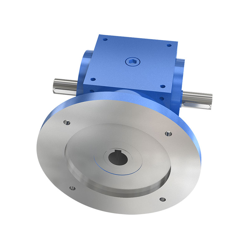
Steering and directional control mechanisms on mobile industrial equipment place a distinct set of demands on a bevel reducer that differ from a stationary conveyor or mixer drive. Response speed, backlash control, and the ability to transmit torque smoothly through repeated direction reversals all matter more than raw torque density alone. The t series steering spiral bevel gearbox is built around this operating profile, using a spiral bevel tooth form to keep engagement smooth as the steering input changes direction dozens of times during a single duty cycle.
Several characteristics distinguish a steering-oriented spiral bevel gearbox from a general industrial bevel reducer:
Because steering systems operate continuously whenever the equipment is in motion, the spiral bevel mesh inside this class of gearbox experiences a high number of load reversal cycles over its service life. Manufacturing the gear pair from case-hardened alloy steel and finishing the tooth surface to a controlled roughness reduces micro-pitting risk under this reversing load pattern, extending the interval between overhauls even in equipment that runs multiple shifts per day.
Industrial equipment maintenance programs built around bevel gear reducers tend to succeed or fail based on a small number of recurring checks, rather than any single dramatic intervention. The following practices consistently show up wherever service life exceeds the manufacturer baseline.
Sampling oil at scheduled intervals and checking for metal particulate content catches early-stage tooth wear well before vibration or noise becomes noticeable.
Shaft seals that begin weeping allow contamination ingress long before a visible leak appears, so a light film of oil around a seal is a signal to schedule replacement.
A gradual rise in housing surface temperature over weeks, even within the rated range, often indicates increasing bearing preload or a developing contact pattern shift.
Most premature bevel gearbox failures trace back not to the gear teeth themselves, but to bearing wear or misalignment that changed the contact pattern long before the failure became audible.
A practical inspection schedule typically includes the following checkpoints:
Recording these checks over time, rather than treating each inspection as an isolated event, is what allows a maintenance team to catch a developing alignment or lubrication issue while it is still a minor adjustment rather than an unplanned shutdown.
Documentation discipline matters as much as the inspection itself. A maintenance log that captures oil analysis trends, backlash readings, and housing temperature over successive quarters turns a set of isolated data points into a trend line, which is far more useful for predicting an approaching failure than any single reading in isolation. Teams that also record the ambient conditions and load profile at the time of each inspection gain the additional ability to distinguish a genuine mechanical trend from a seasonal or operational variation, which prevents unnecessary teardown of a unit that is actually performing within normal limits.
Training the personnel who perform these checks is equally important. A technician who understands why a particular contact pattern indicates misalignment, rather than simply following a checklist, is far more likely to notice an early warning sign that falls outside the standard inspection points. Pairing a documented maintenance schedule with hands-on training in gear alignment fundamentals is one of the more overlooked ways to extend the practical service life of any bevel gear installation beyond its baseline design expectations.
A bevel gear connects two shafts whose axes intersect, while a hypoid gear connects shafts whose axes are offset from each other, which allows a larger pinion and generally smoother, quieter operation.
The curved tooth line of a spiral bevel gear brings multiple teeth into contact gradually rather than all at once, spreading the load transition over time and reducing the impact that generates noise.
A basic visual and temperature check on a weekly basis, combined with quarterly oil analysis and an annual full inspection, catches most developing issues before they cause unplanned downtime.
Misalignment, insufficient lubricant film thickness, incorrect bearing preload, and operating above the rated torque capacity are the most common contributors to accelerated wear.
Yes, when the gearbox is specifically designed with tighter backlash control and reinforced shaft support to handle the frequent direction reversals typical of steering duty cycles.
A miter gear changes the direction of rotation by ninety degrees without changing speed, making it suitable for instrumentation, actuator linkages, and other applications where directional change matters more than gear reduction.
Marking compound is applied to the tooth surfaces and the gears are rotated under light load; the resulting contact pattern is compared against the specified pattern to confirm mounting distance and shaft position are correct.
Housing rigidity directly affects how well the gear teeth maintain their designed contact pattern under load, so a housing that flexes excessively will shorten gear and bearing life even if the gear set itself is correctly manufactured.
Flange-mounted units tie the gearbox output more rigidly to the driven load and tolerate less residual misalignment than foot-mounted units, so the intended mounting orientation should be confirmed before finalizing bearing and housing specifications.
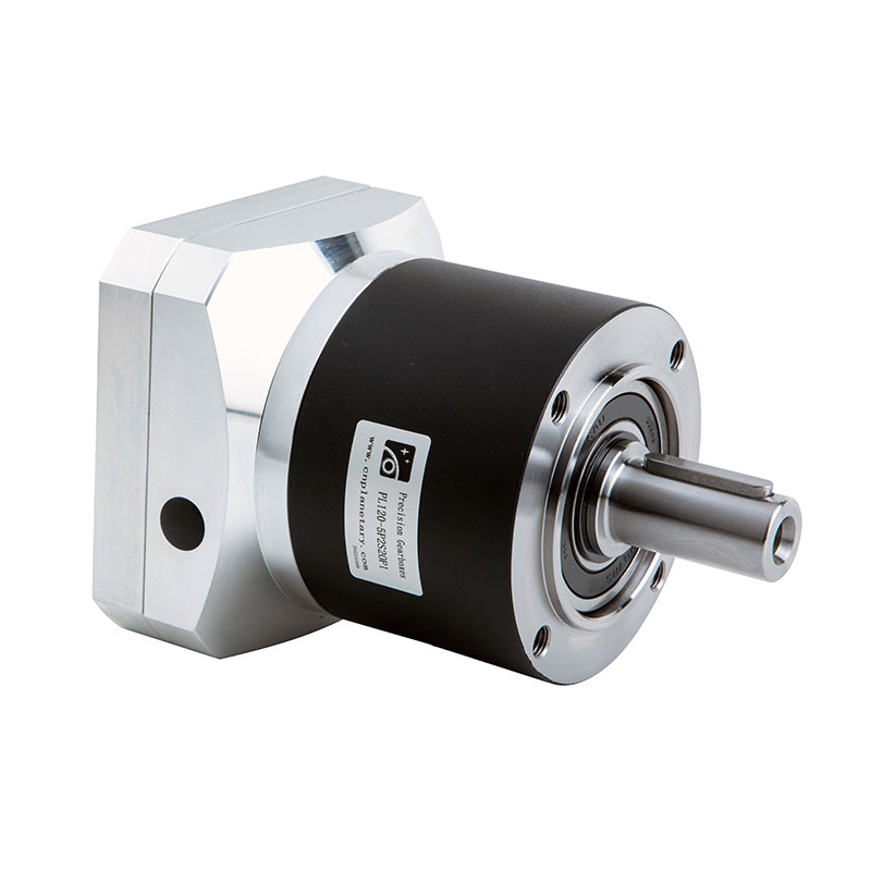
In the realm of mechanical engineering, the planetary gearbox stands as one of the most efficient and reliable components in power transmission systems. From automotive applications to industrial mach...
See Details
With the rapid development of industrial technology, mechanical equipment has become increasingly important in all walks of life and has become a key factor in promoting the improvement of productivit...
See Details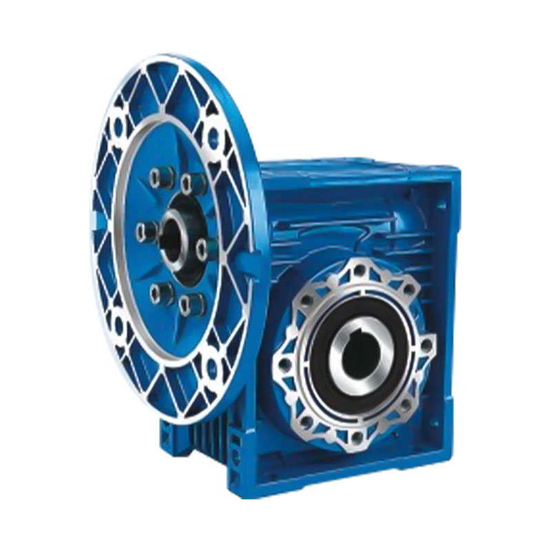
In modern industrial transmission systems, efficient, reliable and compact speed reduction devices are one of the core components that ensure the stable operation of mechanical equipment. With its uni...
See Details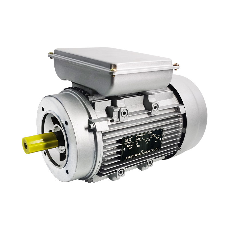
In the huge system of modern electrical equipment, single-phase AC motor is an extremely critical basic component, and its presence is everywhere in all areas of life and production. Whether it is hom...
See DetailsRequest for a call today